
Beam Reinforcement Sheet
The sheet is opened by choosing the menu option Edit|Reinforcement|Beams.
If the beam check has been carried out, it is possible to have a complete control of the checks in the beams for the various limit states.
Specifically, it is possible to examine the reinforcement arrangement in detail, histograms showing the maximum stresses in the steel and concrete acting at the end and mid-span sections of each beam for stress checks, and the load factors for strength checks. The displayed reinforcement can also be modified in quantity and arrangement. Modification of the bars and stirrups can be performed both graphically, using the mouse and the functions available in the sidebar, or by modifying the descriptive data of the bars shown in the corresponding data grids. The initial and final positions of the bars, their number, and their diameter can be changed.
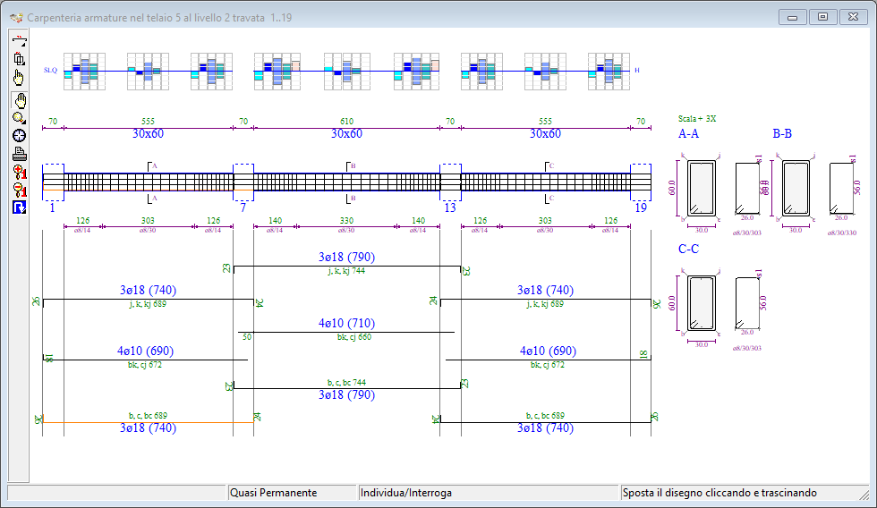
Beam view with verification histogram display
The beams are displayed in sequence, and the drawing contains all the details necessary for a complete definition of the reinforcement arrangement. The selected level and frame are indicated in the title of the display window.
The window contains the usual management components, already encountered in other graphic windows:
- the toolbar, with the buttons associated with the work tools;
- the status bar, which displays information and messages about the current operation.
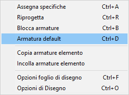
Popup Menu
Right-clicking inside the Drawing area brings up a Popup Menu that allows you to change design specifications, redesign, copy and paste reinforcement between elements, reset default reinforcement, change drawing sheet options, and view the drawing options sheet described later.
Toolbar
The Beams sheet toolbar consists of the following buttons:
 Irons Element: Opens the longitudinal irons tool panel.
 Brackets Item: Opens the brackets tool panel.
 Locate item: Allows you to select an item by clicking on it with the mouse and synchronize all open windows with respect to the clicked item.
 Move the drawing: Allows you to move the drawing by clicking and dragging the mouse.
 Zoom: opens the zoom toolbar.
 Default View: Resizes and centers the drawing proportionally to the window size.
 Print Preview: Enables the print preview of the drawing.
 Enlarge fonts: increases the font size of the characters.
 Reduce fonts: reduce the font size of the characters.
 Redesign: opens the redesign toolbar.
For the use of common tools, what is said in the paragraph relating to plants remains valid.
Change of level and frame
You can quickly change the level and the displayed frame by clicking on the buttons on the command bar.
 to move to the next frame
 to move to the previous frame
 to go to the next level
 to move to the lower level
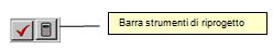
Redesign Toolbars
Clicking the Redesign button opens the redesign action bar, which offers three different actions, explained in detail below.
The functions contained in this bar are very useful as they allow the user to quickly experiment with the effects of different design choices on the currently displayed element, and only on that element, and to finally choose the one that best suits the particular case.
 Assign Redesign Specifications: Opens the sheet, shown below, where you can assign the specifications to be considered in the redesign.
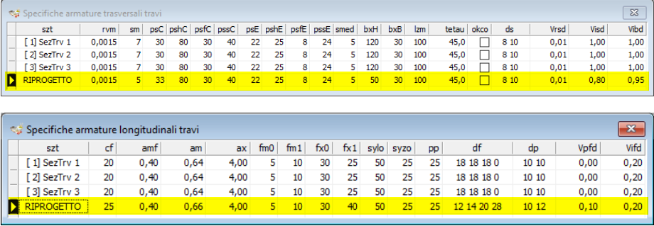
Redesign options for beams
In the redesign phase, the diameters and specifications assigned in this grid will be used, while for anything not reported in the current sheet, reference will be made to the parameters assigned in the Diameters and Specifications sheets of the Project Menu.
 Run Redesign: starts the redesign of the displayed beam only, based on the specifications assigned in the previous grid, leaving the reinforcement on the other beams unchanged.
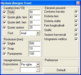
Drawing options
The drawing options are accessible from the popup menu that appears, as already mentioned, by right-clicking on the drawing area or from the keyboard using the
A more general discussion of Drawing Options has been covered in a previous section of this same chapter, to which you are referred for the methods of use and for the criteria for sizing the characters for text.
Numbering and dimensioning
The drawing indicates the number and diameter of the longitudinal bars, the partial dimensions of the rebars, the overall cutting length, and, where necessary, the positioning height relative to the column line. The sections of the beam with uniform stirrups will also be dimensioned, indicated by the number of legs, diameter, and spacing.